The Control Surface: During this discussion we will refer to a control surface, which can be either elevator or flap. With no torque applied about a control surface hinge, the surface will assume a neutral position. If a torque is applied, the surface will change angle (move) until the airloads on the surface balance the torque. The airloads are proportional to the area of the surface, (span x chord) (bc), the chord (c), theairspeed (V), the deflection from the chord line (&delta), and the angle of attack (&omega) of the fixed surface.
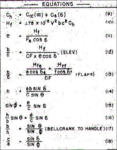
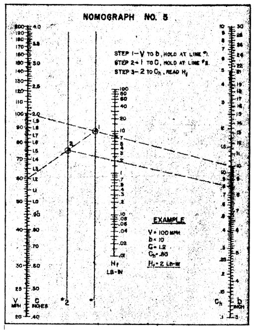
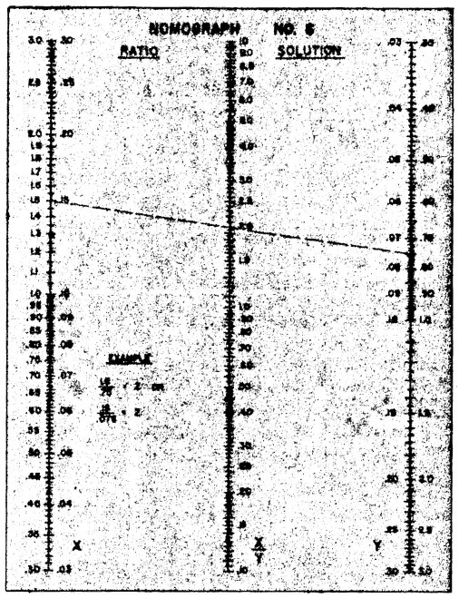
Precise formula is Equation 10 (Nomograph 5). Hf is the total hinge torque. From Eq. 10 we can surmise some interesting surmeece. Hinge torque increases as the square of velocity, and the cube of scale (b.c.c.), also increasing directly with (&delta & &omega). You fly a given airplane twice as fast, you need four times the control force, or build a twice-size airplane and it will require eight times the control force.
Any clues yet? A major breakthrough toward CL system analysis was finding sound data for (Ch), the Hinge torque parameter. This number plotted in Graph (2) provides a coefficient related to control surface deflection and fixed surface (&omega) for known~ratios of hinged surface chord to total chord (Cf/C). When applied in Eq. 10 it gives actual hinge torque in pound-inches, having had "q" corrected for units normally used (inches, and mph). To use Graph (2) determine (Cf/C) using average chords, maximum deflection angles and for now, estimated surface (&omega).
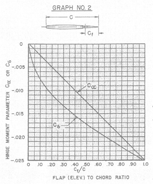
Nomograph 6 is a simple ratio computer, useful in several control calculations. More exact (&omega) is forthcoming. For a stabilator, estimate (&delta) as deflection angle less airplane (&omega). The two coefficients you read from the graph are applied in.Eq. 9 to get (Ch). As an example: if (Cf/C)=.40; C(&omega)=-0.01 and C(&delta)=-.015. We must watch the polarity of these functions, so: "Up" control surface (&delta) is a negative angle, Down is positive. A positive angle (&omega) of the fixed surface (airplane nose up) gets a negative sign (nose down is positive). These have more meaning to man-carrying machines since they must maintain one type of control action, "backstick, up elevator" etc'.
We are more intuitive with our numbers, since we can hook up our system in several conventions, as long as handle action. produces what we want. Back at the ranch, to get Ch for our example, let: (&delta)=30 degrees up and (&omega)=8 degrees nose up. Ch becomes (-.010) (-8) + (-.015) (-30) = + .53. For a stabilator at 30degrees deflection and airplane (&omega) of 8 degrees nose up, (&delta) becomes -30+8 = -22 degrees, and Ch=-.0l5 (-22) +.33. As we said, since we put the horn on either top or bottom the signs are important only during Ch calculation. You might browse through some of your own airplanes for practice.
To round out the first calculation let's make our elevator two different sizes with the same area, to illustrate the effect of aspect ratio. For 50 sq. in. we can go b=l0 and C=5 or b=25 and C=2. OK? At a velocity of 60 mph, Hf for Surface (1)=8.35 lb-in.; surface (2) Hf=3.35 lb-in. One blow for high aspect ratio. If you increased your velocity to 85 mph, Hf would double!
The Pushrod: This essential device, is generally overworked and underpaid. In its best geometry it should be an absolutely straight rod, but this is seldom possible. It is weakest in compression (push), and is treated mathematically by Euler's Equation for Long Thin Cylinders in compression. Failure is due to buckling, or springing out of a straight line, and having done this it can carry no larger load. It should be obvious that a buckled control rod will create no more surface deflection, generally allowing the surface to "back off" or lose angle. About a third of our problems are explained by this.
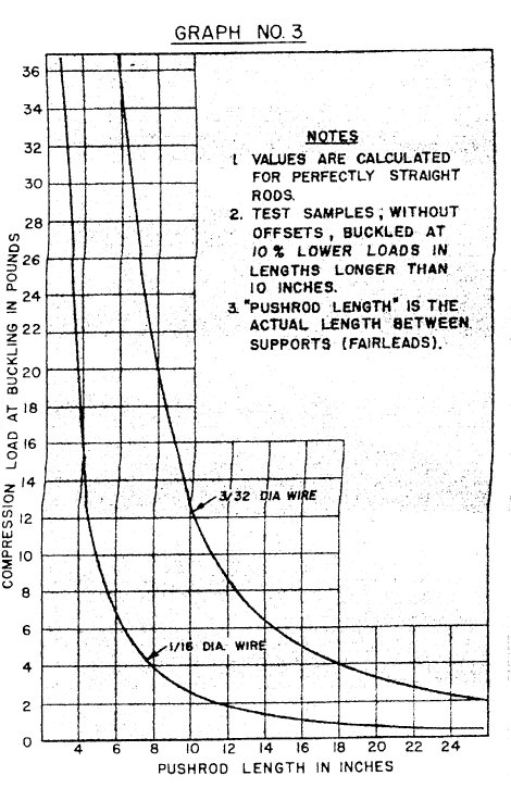
Graph (3) presents calculated buckling loads for two sizes of common pushrod wire. We built a test rig and measured several diameters in various lengths. Results were: (a) We can get only 90 percent of calculated values because our wire isn't straight enough as we buy it; (b) Unsupported rods with as little as 1/8-in. offset, buckle at such ridiculously low figures, they are almost unpredictable; (c) our salvation lies in reducing unsupported rod distances with fairleads. With any design you know pushrod length, right? We need to know pushrod load. Comes the first compromise. We attack the problem by establishing a control horn dimension (e) which will allow pushrod load (Fr) to be a "safe" value, that is, below buckling load. Take your pushrod length, assume one fairlead in the exact center, enter Graph (3) at a length equal to the longest segment of pushrod (in our case 1/2 the total length). Read the proper curve for buckling load. Now look up Equation 11, plug in Hf, Fr, and Cos (&delta). Cos (&delta) is necessary because as you move the control surface, the effective control horn force arm decreases proportional to Cos (&delta). We are still solving for maximum loads.
Continuing our example, Hf=8.35, we pick 16-in. long 1/16-dia. pushrod so that Fr for an 8-in. rod=4 lbs. At (&delta)=30 degrees Cos (&delta)=.866, so e=2.4 in. Oops! So we have a kooky elevator, but let's thrash it through.
Use a 3/32-in. pushrod, Fr=20 lbs and e=.48in. A bit more reasonable, yes? Just as a matter of f'r'instance our other elevator would have needed a .97" horn with the 1/16-in. dia. pushrod.
The Delicrank: The force to actuate the elevator is amplified by the belicrank, is transmitted by the pushrod and comes from a differential tension balance between the lines as one end of the handle is moved away from the airplane. Note, if there were no elevator load, each line would carry a load equal to 1/2 CF in all positions, assuming no stops or restrictions to movement. The maximum force which can be used to move controls is the full Centrifugal force (CF) applied to one line in tension. The other line becomes slack and exerts no load on the system (assuming the aerodynamic drag tension components to be equal). This key opens the next door in our system analysis.
To establish bellcrank dimensions we utilize two sets of requiremcnts, spiced with some individuality. Equation 12 defines the relationship of bellcrank dimensions to the already fixed "numbers". If we have a 40 ounce airplane on 65-ft. lines; CF=9.l lbs b/c=2.2. Spelled out we need a bellcrank where (b) is not less than 2.2 x (c). But we don't have (c) yet! Comes the intuition backed by experience. The proof of the following is left up to the reader.
A study of bellcrank and horn geometry will show that the best relations between bellcrank travel (&phi) and elevator travel (&delta) occur when C is equal to or smaller than e. See Eq. 18 for relationship. Note also that angles are related by trigonometric functions since we generate a linear displacement by rotary motion. When c=e, each degree of bellcrank travel produces one degree of elevator, if the approach angle of the pushrod is parallel to a line between hinge points and the pushrod holes at neutral are square with this line. Good systems are possible with c's down to 0.6e. Below this it begins to take too much belicrank travel to produce elevator motion, although it could be useful to correct a sensitive design that is not totally unstable.
In cases where (c) is larger than (e), elevator angles quickly reach 85 degrees, the action becomes too "fast" at the ends, and the system is prone to be inadequate in producing useful control forces. So, we have narrowed the selection of c to a range between e and 0.6e. For trial values try 5 steps like e, 0.9e, 0.8e, 0.7e, and 0.6e or just pick one from experience. One other point; if b/c comes out larger than 3, you're really in trouble because standard bellcranks don't provide b/c much over 3. If this is the case, your solution is to establish a longer control horn, reducing pushrod loads, thus requiring less mechanical advantage at the bellcrank. Or, you can build your own custom bellcrank.
Another significant argument for reduced pushrod loads is hole wear. The lower the Fr, the longer a system will operate without wear. The practice of bushing the bearing holes leads in this same direction by increasing the hole surface area, thereby reducing the stress level, accomplishing the same reduced wear.
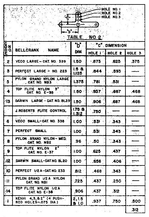
To pick a bellcrank, having established a reasonable (c), use Table 2 which lists most of the commercially available bellcranks and their dimensions. A horn with the proper (e) may be found in Table 3. Note that dimensions shown for external type horns are from the base of the horn to each hole. You'll have to add on 1/2 of the elevator thickness or specifically the distance from the horn base to the center of the hinge to get the proper (e) dimension. It is highly desirable that your b/c was less than one (1.0). In this case a bellcrank can be selected that will provide a b/c larger than the required b/c allowing a large safety margin. In such a case simply establish (c) as before, pick a bellcrank to suit your whim and record its b/c ratio.
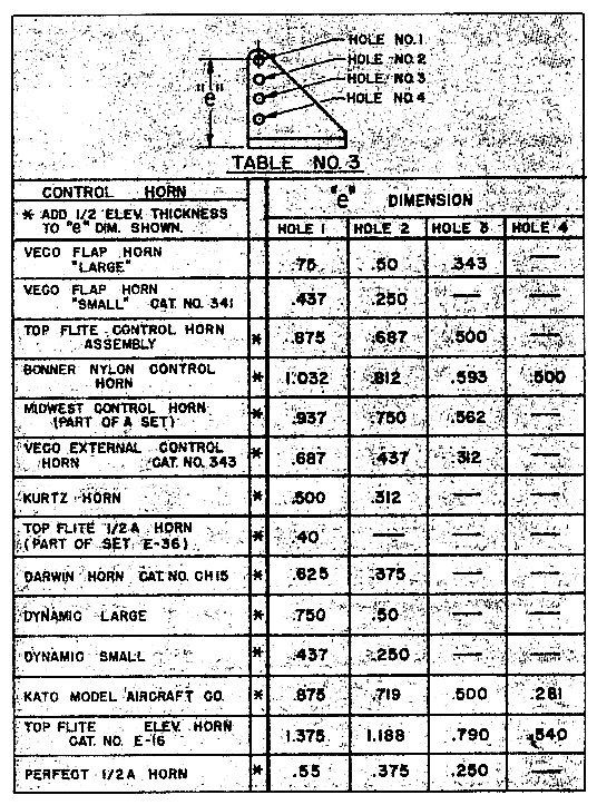
In our example we will pick c=e (.438) so b=.97" (roughly a 2-in. bellcrank). This will give a marginal system with stiff "feel". From Table 2, the TF Nylon 2-in. is about the only exact copy available. This could be used with Veco small horn, a Kurtz horn or a Veco external horn on a 1/8-in. elevator. If we were carrying an 8 lb.-in. torque, the Veco small horn would probably not hack it due to the 1/16 wire carrying the torque. In fact for such a kooky elevator, we would probably go up to a 3/4-in. horn and a larger bellcrank to reduce pushrod wear. However, we'll carry this one through to completion, since it allows us to point out critical areas for compromise. Actually we are very close to the end.
The Handle: To complete the system we must pick a handle, specifically the line spacing to correctly correlate your natural motions to full elevator travel. To this end, you'll have to do some educated guesswork. Each of us has a hand-motion computer built into our brain. We've trained it and expect (or prefer) the airplane to hit its maximum control response, at the point of handle travel we like (&theta). The game then, is to find your own preference. Studies indicate it will be between 10 degrees and 30 degrees, averaging less than 25. My own preference seems to be 22 degrees and most people who have test flown my ships, prefer "faster controls" (smaller &theta). Our sample system, using my 22 degrees &theta would use a 2.68" line spacing (h=l.34), such spacing being twice h. We have just established dimensions for a complete control system. However, this system is just exactly right for all given parameters at 60 mph. At higher speeds we would be in trouble, at lower speeds, no problem. The reasons are not readily obvious, but consist of one large fact. We set up our controls to just reach pushrod buckling under the conditions specified. This is the limiting factor in the whole system since Fr is the maximum force which can be applied to the elevator horn.
We can increase pushrod force with more speed or a larger b/c at the bellcrank, but since Hf increases in the same relation as CF, our pushrod will buckle before reaching maximum (&delta). A further problem rears its ugly head when we try to hit a square corner coming into the wind out of level flight, with a marginal system. The CF comes from velocity relative to center of circle. Heading into the breeze causes this velocity to decrease, hence CF decreases. The elevator sees actual velocity of the airstream which increases. With increased Hf, decreased CF and a marginal Fr, you can't get full control! We recommend a tentative solution which applies a bias factor to Hf for stunt, combat and sport ships "that fly on their backs." Until further notice multiply Hf by 1.4 and then design your system.
The additional 40 percent should keep you out of trouble 98 percent of the time without overdesigning the system. We don't anticipate any problems with Rats, TR's, Carrier or Trainer types, unless elevators are a very large portion of the stabilizer. Design for a speed 10 mph over the highest you expect. Speed types have a problem to be covered at a later date, basically due to lack of torque at the control unit and high airspeeds.
Flaperoonies: Precision aerobatic types have a longer chore, since flaps also require force to move. Flap Hf and F are computed in the same way as the elevator. We suspect from preliminary aerodynamic checks that most contemporary ships don't change angle of attack during a maneuver, but you could assume maybe six degrees just for safety. Equation 13 is "good" only if you use a flap horn for transfer in 1-to-1 ratio (Fig. 3) (case I), or if you connect a-la late model T-Bird with direct connection between bellerank and elevator and tie your flaps to that same rod. The bellerank to flap rod must be designed to carry both flap and elevator loads for case (1).
Good design practice says use either equal flap and elevator travel or use more elevator travel than flap. So you must pick some geometric relation between (f) and (e) as well as relating both to (c). Takes a little judgment and a little more work, but you guys are in more danger than the rest, too. You might run a check for overhead maneuvers by assuming 1g (CF) and an airspeed around 40 mph. In most cases the enlarged Hf factor should cover you.
During overhead maneuvers, the lack of turning ability can be traced to low airspeed and one g unit taken away by gravity. It begins to appear that a correetly designed acrobatic airplane would fly better at 60 mph, than at the 45 to 55 we use now. At best, there is an excellent chance that the conventional design can fly better than it does right now.
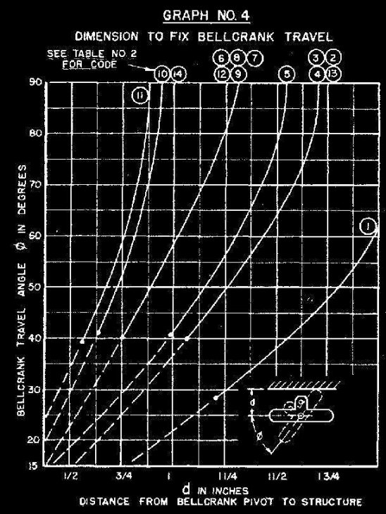
Details: Graph (4) provides data to locate a set of stops at the bellcrank to provide known maximum control angles, or simply to provide enough clearance. Eq. 15 computes the bellcrank angle (&theta) for values of (&delta) and (e/c). For our test case &theta=&delta or 30 degrees. If we used the TF 2-in. bellerank, we'd locate the mounting bolt 5/8in. from a rib restricting its motion, and thus the elevator to 30 degrees. The dotted portion of each curve indicates that the pushrod arm of the bellerank must be cut down to fit.
It is interesting to note that all bellcranks except the old Kenhi unit have an unmodified minimum &theta within one degree of 40. lt is recommended that a resilient pad, such as urethane foam or foam rubber 1/4" thick, faced with shim stock, be used as stops. This will decrease the shock load on the lines during sharp action.
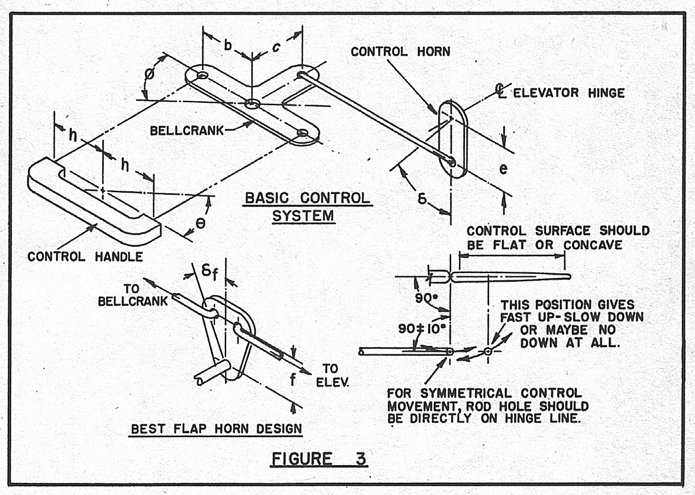
The sketch in Fig. 3 illustrates another critical feature of the system. For symmetrical up and down angles the pushrod end in the horn should fall on a line 90 degrees from the line connecting the horn hole and the bellcrank. If installed as shown in an aft location, the effective torque arm has already traveled a good part of its arc, and your actual (e) dimension is longer than you thought. Such placement can be used to advantage IF you desire more control in one direction. lf placed aft of the hinge you'll get fast up and slow down. Placed forward of hinge the opposite is true. Of course for the horn on top all bets are reversed!
Summary: Elevator size and maximum angle are fixed values for any given airplane and mission. So Hf is fixed. Pushrod buckling load is the first weak link, so it must be designed by computing an (e) dimension to suit the physical requirements. The pushrod can be strengthened by shortening unsupported distances with fairleads (guides) and/or increasing the wire diameter. Pushrod loads can be reduced by using a larger e at the horn, and wear can be further reduced by increasing the thickness of material at the bearing holes, either bushings or thicker material. The design b/c ratio is the second area where trouble can be eliminated (or caused). It should be set up so that the required b/c is less than one (1.0), and a bellcrank should be selected with a b/c ratio larger than 1.5. These additional mechanical advantages should prevent loss of control under almost any unexpected condition of flight. IF you find that the system gets out of hand in a practical scnsc, you can always back up closer to the exact values computed. Finally, your personal handle travel preference should be established by experiment and designed into ALL of your airplanes.
Sorry, I can't improve on this quality.
DES!GN PROCEDURE
1. For elevator-chord ratio (CF/C) and predicted maximum angle of deflection calculate (Ch), using Eq. 9 and Graph (2).
2. With airspeed, elevator dimensions and Ch calculate Hf-(Nomograph 5). (See text for Stunt and Combat.)
3. From pushrod size and geometry, determine Fr (Graph 2).
4. Establish (e) using equation 11, at the maximum angle from step 1.
5. Calculate Centrifugal Force using airplane estimated weight, line length andairspeed. Nomograph 3. [Part I]
6. Calculate b/c from eq. 12 or if flaps are used, eq. 13.
7. Browse through table 3 and pick a horn with proper e dimension.
8. As a trial c, pick out a bellcrank with a c dimension so that e/c=1. Check that bellcrank for b/c required. If the bellcrank's b/c is larger than your required b/c, you're in. If not, try another. Use Nomograph 6 to speed calculations involving ratios. As proved earlier c should be between e and 0.6e.
9. With bellcrank selected you can establish handle dimension (h), designing it with Eq. 14 to move your favorite angle (&theta). Remember (h) is 1/2 of the actual line spacing.
10. Using Eq. 15 establish bellerank travel angle (&theta).
II. If desired, a blocked system can be made using locating dimension from Graph (4), or at least guaranteeing enough clearance.
Sorry, I can't improve on this quality.
Part 3 will include data on single-line systems, aerodynamic balance of control surfaces, and the physics of flight at altitudes above the handle. These first articles cover those items which are peculiar to CL airplanes. Future articles will establish firm design data for the airplane itself from minimum turn radius to landing speeds.

![]()
![]()
![]()
![]()