The kit - The motor and wheels - E & OE - Chassis assembly - Body assembly - Painting - Conclusion
As an active, competitive aeromodeller with many other interests, my model railway interest had lain dormant for many years, with an occasional 'rest' of building rolling stock, mainly 'OO', with a spell of Scalefour. Some 10 years ago, I switched to 'O' gauge and wished that I had done so sooner. I managed to obtain a second-hand, but mint, Vulcan/Underhill GWR Pannier Tank kit (8750 class), This was a superb, beautifully engineered kit. When I eventually finished it (there was never any need to rush and I needed a rest from contest deadlines) I needed something else. OK, so much for the recommended 'starter' (I had built 'OO' locos), so how about something with outside motion?
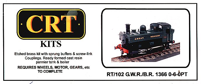
Years ago, I built a K's 'OO' GWR 1361 dock tank and always fancied the 1366 pannier version for 'O' gauge. I couldn't find an Underhill kit and the ABS range based on them seemed to have gone, so I settled for a CRT kit.
As I now had a well established aeromodelling website, it seemed a good idea to write up my adventures for a future possible model railways page(s). I rather regret the fact that I didn't do this with the '8750'. I've written many reviews for various magazines and they have always appeared as a finished article. So, let's try writing a review 'as it goes', warts and all.
Here is the start which will be updated approximately once a week (or so). See date above.
The kit was ordered from West Coast kit centre as a basic kit, but with plunger type pickups. This was because the plungers were advertised as an upgrade. It was the right thing to do because the standard pickups consist of printed circuit board and phosphor bronze wire 'scrapers'. These have to be stuck on the outside of the frames and would be rather obtrusive apart from possible conflicts with the brake gear.
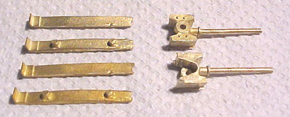
Supplied are one set of brass frets for bodywork and footplate, one set of nickel silver frets for the chassis and coupling/connecting rods, one pack of various whitemetal castings (mainly bodywork), one set of lost wax castings for buffers/couplings, and a set of turned brass fittings for chassis spacers and axle bearings. Finally two resin castings for the tank assembly and smokebox saddle. Instructions minimal but probably adequate if you've already built another loco kit.
Most of the various bodywork plates have lines of rivets on them. The positions of the rivets are etched on the rear of the plates as a dimple. You need to emboss the rivets through onto the outer surface using some form of punch.
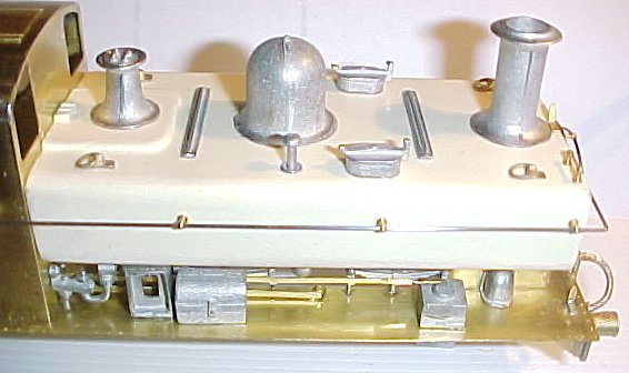
Ordered wheels, motor, gears and flywheel from Tower Models. The gearbox was a Maskits unit with Romford 30:1 gears. This is a simple fold-up unit which was easy to assemble and needed no adjustment to the gear mesh. Gears are attached to shaft and axle via a grubscew. The solid brass flywheel had no obvious means of attachment but was easily fixed with a spot of epoxy.
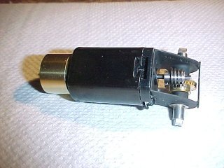
Motor and gearbox.
The wheels were Slaters which really need no further comment. I made new balance weights from plastikard which were fixed in place with thick cyano. I blackened the wheel rims with gun blue.
Some thought went into the position of the motor/gearbox unit. With the flywheel fitted, there was really only one position which would leave the space under the boiler and the cab interior clear. This was with the drive taken to the rear axle and the gears underslung. The motor is angled forwards into the boiler at an angle which allows the flywheel to clear the inside. A further consideration here was the position of the pickups on the rear axle. By setting all of the pickups above and behind each wheel centre, everything fits.
As it was rapidly becoming clear that this review would have quite a lot of negative things to say, I decided to put them all in a section of their own so that any readers can read this bit first, or skip it completely to suit their preferences.
I was not impressed to find that I had to emboss the rivets and that a suitable tool would cost almost as much as the kit. This point really should be stressed somewhere.The word 'etc' (in lower case too) in the box top art really doesn't quite cover this.
The smokebox saddle casting was far from square and very rough. It didn't want to fit the tanks at all well. The resin tanks themselves were far from square and one of the sides far from vertical. The radii on the tank sides were all different and more like bevels.
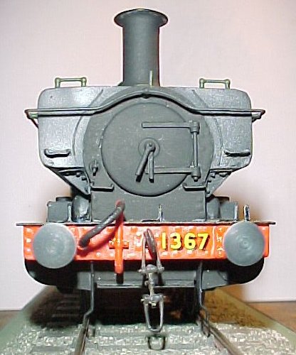
Buffers appear to be very heavy and possibly over scale compared to my existing '8750' class pannier. I couldn't find any dimensioned drawings but checking against various GA drawings they do seem to be oversize. They are some 1.5mm longer than scale, but that can be fixed with a spacer behind the splitpin that anchors the stem. I ordered a set of buffers from the Slaters range as a possible alternative. When these arrived they certainly looked better.
Chalk and cheese.
I put both sets together for a proper comparison and found that the springs supplied for the kit buffers became coilbound before the bufferes were even half compressed. Then I found that the splitpin supplied to anchor things wouldn't go through the hole in the stem! By shortening and stretching the spring I got it working, but why should all this be necessary? The Slaters buffers just go together and work! What's more, the stem is retained by a nut, which means that you can adjust the static length. I now have to decide whether to 'waste' a set of Slaters buffers on something that isn't going to end up right anyway. The decision was made for me when I discovered that the base of the kit buffers are not square to the shank, so a lot of work would be required to make them sit square on the bufferbeam.
In the instructions there is a reference to the supplied motor mount being positioned over the centre axle. No motor mount was supplied. Mounting over the centre axle would make it very visible in the space under the boiler.
The four etched parts supplied to laminate the buffer beams were all different. The various etchings that make up the cab really didn't match up well at all. The front and rear were different widths and the folded-up floor would not fit inside the cab. Examination of photos of the real engine revealed that the crew stand on the footplate and the floor isn't raised, so the folding up floor was wrong anyway. The bunker rear was rather wider than the cab and with strange cut-outs. Blowing up a scale drawing of the engine to 7mm scale (a pity that the drawings in the instructions are way under scale) and printing out revealed that the bunker was actually about 3mm shorter than scale. Apparently, the excess width on the bunker rear was to allow it to be folded around and butt-joined to the sides.This is partly shown in the instruction diagrams but not mentioned in the notes. This will leave gaps to be filled in how?
All of the etched brass parts for the footplate/cab/bunker unit are in a very heavy gauge material. Apart from shaping and finishing problems, get ready for burned fingers.
Balance weights for the wheels are included as part of the chassis frets. These appear to be intended for wheels of larger diameter and probably more spokes, since they aren't long enough to cover four spokes as required here. I later discovered that the brake shoe castings also seem to be intended for larger wheels and need reprofiling. The method of attaching the brake shoes is via a whitematal casting which is nothing like scale.
The arrangement of thin side frames for the chassis, coupled with soldered spacers, rather than bolted, seemed rather fraught with problems. The spacers have 6 BA clearance holes for the 8 BA fixing bolts. See later.
That scale drawing also showed that the footplate was 2 - 3mm too long! That's 4 - 6 inches in the real world.
Almost on my first look at the kit contents I realised at the back of my mind that something looked wrong about the etches supplied for the coupling rods. At an early stage of assembling the chassis, I realised that the holes for the crankpin bushes were much larger than the bushes. The bushes are 2.4mm dia and the holes for them were 3mm! I contacted the kit manufacturer who told me that the kit had been taken over from another manufacturer (where have I heard that before?). They had considered redesigning the chassis etches but felt that this would introduce other problems. They also stated that the chassis would work as supplied!
The bushes supplied for the axles have a flange that is so large that it fouls the back of the crankpin bolts in the wheels.
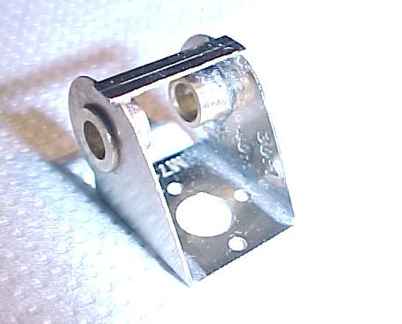
The chassis sides are rather thin, (I originally wrote 'but adequate' here but see later), nickel silver etches. The joiner/spacers are turned brass with a spigot that engages holes in the chassis sides before soldering. The spigots are too large (or the holes too small) so that some ajustment is necessary. One possible source of mis-alignment. The holes that locate the turned axle bearings then proved to be too large for the bearings. We now have two possible sources of mis-alignmment. I have always read that the great advantage of etched parts is that they can be made to match exactly. Assuming that the chassis sides and coupling rods (all on the same etch) are the same, I'm still wondering how to ensure that the wheel spacing matches the rods.
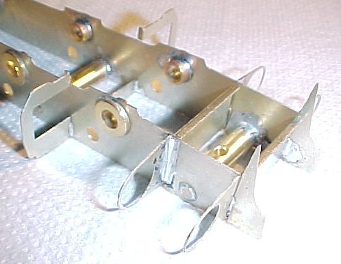
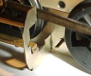
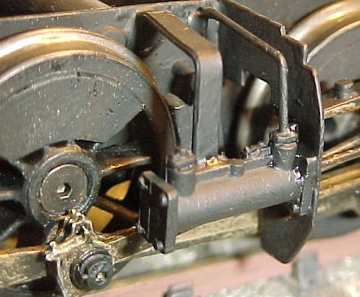
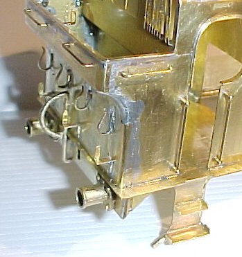
Spacers and axle bearings. The small hole between the spacer and the bearing is for the plunger pickup. The larger hole is at the rear of the chassis and appears to have no other purpose than to get in the way!
My misgivings were well founded.There is really no way of holding the assembly of side frames and spacers together while you solder and, therefore, no way to ensure that it is aquare. I soldered the axle bearings in place on each side frame and then soldered the spacers to one frame. These were checked for squareness and then adjusted as necessary, The problem is that the solder which wicks into the joint pushes the two parts away from each other. Applying pressure doesn't halp, or makes things worse.
With the spacers somewhere near square, the second side frame was perched on the three spacers and soldered. Again, no way to get things square to start with, let alone keeping them square. After much re-adjustment things were beginning to look reasonable - except that the whole chassis was twisted. Nothing to it but to remove one frame, readjust the spacers and try again. There was still a slight twist! I had started this exercise late at night (as usual) and gave up at 7 am, still far from satisfied.
Next evening. I attempted to correct things by putting two screwdrivers through the outer axle bearings and gently twisting. Well, the intention was to obtain some idea where the problem lay and then find a way to fix it. Just when I thought I might be naking progress, the sideframes buckled. Maybe they were too thin.
The obvious move here was to tear everything down to the component parts and start again, after straightening the frames. The thought of making new frames, possibly from thicker material, also occurred. I managed to straighten the frames in situ, by eye and using a straightedge. By a process of gently twisting the frames and applying heat to the joints, I got the twist down to manageable levels.
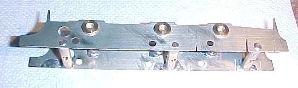
Chassis.
Those sloppy bearing holes now became useful as I was able to move each one in turn until I had all six wheels sitting in contact with the obligatory sheet of glass. This was a very laborious process involving an uncounted number of times that the wheels/axles had to be removed and refitted. I learned years ago that you don't apply heat to things with the wheels fitted! I finished at about 5 am this time. It remains to be seen whether the wheel centres match the coupling rods.
Included in the fret for the frames and rods are etches for the front and rear ends of the cylinders and the motion bracket. Etched slots allow the whole assembly to go together like an eggcrate. The slots are considerably wider than the thickness of the material which suggests that they were originally planned for thicker material. The result is a sloppy fit with lots of variation possible. Now, logically the two ends of the cylinders, the motion bracket and the centre driving wheel axle should all be in a straight line - they weren't. By extending the slots and the usual process of adjust, resolder, adjust, etc I got things somewhere near.
Cylinder ends and motion bracket.
I tried using the included etched brass plates for the cylinder wrappers, but soon gave up and replaced them with thinner material. All the photos of the real loco that I have seen have rather obvious dents in the sides of the cylinders, so the real one must be pretty thin.
Cylinders.
The slide bars and crosshead are all brass castings. What isn't immediately obvious is that the moulding sprues on the slide bars are intended to fit in holes in the cast ends of the cylinders (whitemetal). Cut off the sprues at the end of the bars at your peril! I did and then found that the bars are too short. Those instructions were now looking sadly inadequate. I now had to solder pieces of brass wire onto the ends of the slidebars to make them reach the cylinder.
Slide bars and crossheads.
I made up the coupling rods using pieces of 1/8" o/d brass tubing to bush the holes. The system of laminating the rods from three layers of etchings is one I have met before and don't like. In this case the bushes halped to hold things together. After tinning the centre lamination I coated the outer laminations with a thin layer of 'Fluxite', clamped things together and sweated the whole lot together. Much better than my last attempt but, after cleaning up with an assortment of files, the laminations are clearly visible.
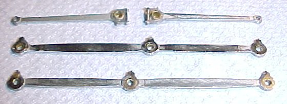
Coupling and connecting rods.
I tried a dummy run of the rods, wheels, etc and found that assembly was not going to be easy and the slide bars needed to be moved. I also discovered that the crankpins foul the axle bearings. All the Slaters wheels that I have seen previously have the crankpin bolt recessed into the back of the wheel and the bolt screws into the wheel, not so here. I will have to countersink the bolt and secure the bolt to the wheel so that I can screw the nut onto it. Does NOTHING fit on this damn kit?
There was more to come. Large amounts of the motion bracket needed to be removed to clear the rods. Those meagre instructions tell you to remove the bottom of the bracket so that it does not reach the chassis sides. They don't tell you how much, or that this is to clear the coupling rods. You are not told that a notch needs to be cut in the top of the bracket to clear the rods. All this is nothing like scale as the bracket goes under the rods to the chassis and there is no chunk cut out of the top. Apparently the crank throw is rather larger than scale. Just which loco is this chassis kit actually designed for, certainly not this one? Things would be bad enough if it actually went together properly.
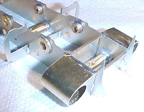
Skeletel remains of the motion bracket.
My fears were realised in that the wheel centres didn't match the rods exactly. After some experiment, it became clear that the left rear axle bearing needed to move forwards. That was fairly easy but, of course, the chassis no longer sat on my sheet of glass without rocking. Back to the solder, test, solder, test until I got it square again. None of this would have been necessary if the holes in the chassis side etches had actually FITTED the supplied axle bearings.
I discarded the flimsy, non-scale, castings supplied to attach the brake shoes and drilled holes in the chassis sides for a conventional straight-through brass wire to support the brakes. Maybe I'll add a cosmetic plate around the wire.
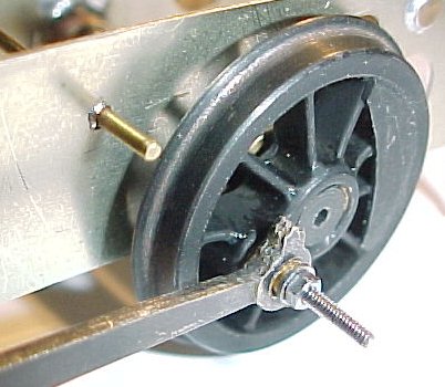
New brake suspension.
Once again I got back to the situation where I needed three hands because of the need to balance the brake rigging between the brake shoes while simultaneously keeping the shoes clear of the wheels. The brake rigging then needed to be truncated because it refused to go through the gearbox. I got things more or less right, although one shoe is rather further from the wheel than it should be. It does help to disguise the fact that the shoe wouldn't fit a wheel of this diameter anyway!
All sorts of issues now emerged. I had to move the slide bars outwards to get enough clearance for the front wheel crankpins. I then had to joggle the piston rods inwards so that they moved smoothly in and out of the piston. I filed down the crankpin bushes to give a good fit on the rods at the front and rear axles. After some thought I then removed more material from the front wheel bushes so that they would clear the rear of the crossheads. I reduced the length of two bushes for the centre wheels so that the two bushes back to back (or, more accurately, front to front) gave a snug fit on the coupling and connecting rods together.
The centre and rear axle crankpins were finished off with Malcolm Mitchell cast crankpin nuts. The front axle crankpins were left without any method of securement. By careful adjustment of the rods they are retained by the other two nuts and, all being well, can't move out and foul the crossheads (well, it's worked so far).
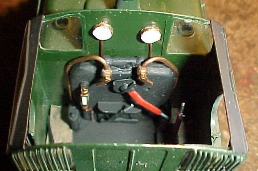
The slight matter of adding the vacuum pump to the right side motion bracket was almost simple. A piece of wire soldered to the crosshead served as a piston rod. The representation of the bracket and pipework which form part of the casting weren't long enough (surprise!) so I extended them with brass strip and wire and took the opportunity to continue them along below the footplate and attach them to the chassis side.
Vacuum pump with extended parts.
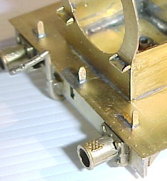
So, dismantle the lot, paint matt black and reassemble. An hours running on a static test rig removed the tight spots and it actually works. However, there is a lot of wear evident on the wormwheel and it seems that the worm supplied (in fairness, not part of the CRT kit) is rather short so that the ends of the thread tend to machine the wheel.
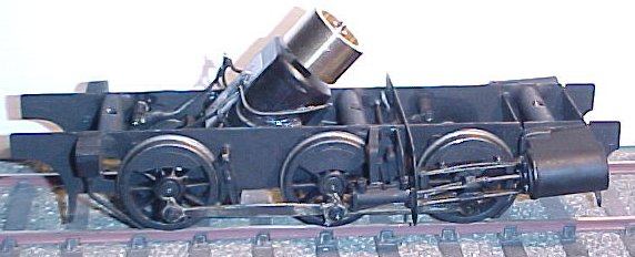
Finished chassis. Temporary wiring terminations to allow easy test running.
The problem with the rivets is that the etched indentations on the reverse side are the only indication of where the rivets are. A web search found suggestion on an American website to use an old ballpoint pen to emboss rivets. This produced rather heavy and indistinct results. I used darning needle in pin chuck. This was better but tended to distort metal surround. Compromised by producing rather small indentations as a marker so that external rivets can be added later if desired.
Bent up footplate valences with Schluter pliers. Not too difficult and small enough to correct any variations when soldering.
The buffer beams are laminated from two pieces. The two outer parts were etched with rivets to be embossed. By sheer accident, I discovered that they were marked 'F' and 'R' (front and rear). I matched these to the two plain items as closely as possible.
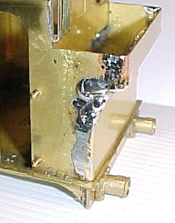
There was no way that the moulding supplied for the smokebox saddle was going to be usable, so I discarded it and made up the saddle using the two pieces of brass supplied for the firebox sides. These were actually too short for the firebox, but the right length for the saddle. I later added a rear plate to fill in the hole. I made up new, correct length, sides for the firebox from sheet brass.
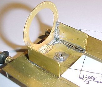
Smokebox saddle. Why not do it this way anyway, rather than supply a useless chunk of resin?.
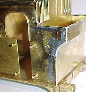
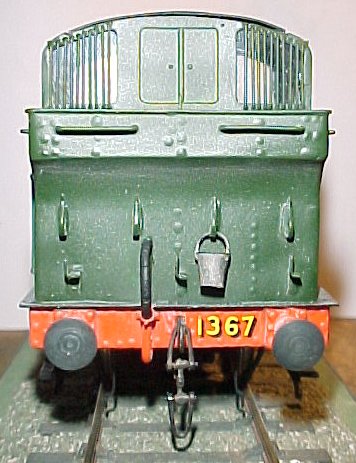
Cab front and sides are bent up from one piece. Immediately we have the problem of controlling the finished width. Even by folding as closely as possible, the cab sides ended up further apart than the cab rear. With absolutely nothing to position the cab on the footplate. I tacked the front in place level with the cutout and as close to the centre as I could manage. It was becoming painfully clear that the footplate was wider than it should be as well as longer.
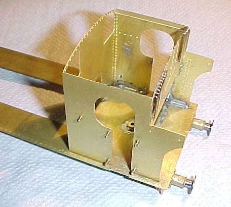
Basic cab.
Having got the basic parts together, the bunker was a little narrower than the cab itself. Comparison with my 7mm scale drawing now revealed the fact that the bunker was still shorter than scale, even allowing for the folded round sides of the bunker rear. This, plus the too long footplate meant that the already excessive overhang at the rear was going to be very noticeable. My answer here is to insert pieces of brass into the join between the sides and rear to make the bunker slightly longer than scale to reduce the overhang. Well, it wasn't going to be right anyway. I left out the unscale floor, it didn't fit.
Bunker with added material |
Finished item |
My mistake here was in assuming that the bunker could be easily filed to shape. Alas, solder is not easy to file and I ended up using up a lot of scalpel blades hacking it into shape and finishing with a file. Comparing the finished item with my scale drawing produced a pleasant surprise in that it is actually almost spot on in length! There are a lot of minor imperfections in the side of the cab and bunker but I console myself with the thought that most real locos are just like that - especially preserved examples.
I then had to risk messing up the whole thing by soldering the beading around the edges of the bunker and the top of the cab door openings. These were supplied etched with a groove along their length and proved surprisingly easy to add. The strip around the cab windows was bent to shape and sprung into position. The bunker edge simply required the asbestos fingers that all modellers are born with.
The sides were etched with a thinner piece at the top to ease the bend into the roof. The problem was that it didn't extend far enough round to make it practical to locate the roof with two strips of brass as intended. It was also all but impossible to get a smooth curve. My original fix was to add strips of brass to the tops of the sides to extend further into the roof and help bending but this didn't really work.
I removed the extra pieces and replaced them with strips cut from the edge of the roof (which included etched grooves for the rainstrips). By building up with solder and then fitting the roof with two locating strips I was the able to profile the whole thing with a file to something like the correct shape. I didn't dare spoiling any of this with more soldering, so the rainstrips and roof vent were glued in place.
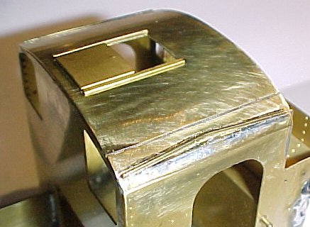
Finished(?) roof.
At this point there was still a lot of 'furniture' to be fitted. The etched lamp irons and fire iron brackets needed a lot of fiddly cleaning up. There is a reduced size scale drawing included in the instructions which give a vague indication of where these go. However, every loco was slightly different so you need to refer to photographs. That accounts for a total of 10 lamp irons and 4 fire iron brackets. Lost wax castings are supplied for the front and rear vacuum pipe fittings, with blackened springs (a la Slater) for the pipes. These are lacking in detail, so I replaced them with items from Laurie Griffin although his representation of the pipes is not as good.
There is a mention of a reversing linkage in the instructions but none seems to be included. I made up a representation of this and the sandbox linkage from scrap brass. Note that at least one loco (1368) seems to have had the reversing linkage on the left (rather than right) side.
Whitemetal castings are supplied for the ejector pipes. I replaced these with brass wire so that they could be soldered to the footplate. That left two steps to be soldered to the front of the smokebox and four handrails around the bunker and I could put the soldering iron away.
|
|
Front and rear 'furniture'.
And now the bad news. If you have already built one or more etched brass kits, you may have some idea of what to expect with this one. However, don't expect precision etchings which can be easily soldered with a reasonable soldering iron. You may already have got the message that precision is not a feature of this kit. There is another feature which is not immediately obvious. All of the etched parts are in a material that is about twice as thick as most other kits. This means that a lot of work is needed to clean parts up and, by the time you are close to finished, a lot of heat is needed to solder things. Soldering such things as lamp irons on to the rear of the bunker means that the whole of the considerable mass needs to be heated up to get a good joint. You then get a large amount of solder deposited suddenly onto the surface and a lot of further cleaning up needed. That's if you manage to hold things in the right position while the solder sets!
Getting the tank moulding to fit took some work. I sanded the sides of the tanks to get them vertical and rounded the edges off. There was a taper in height towards the tank rear which I decided to leave. I eventually got a reasonable fit but the whole thing site a little high because the tank is actually deeper than it should be. The material used does not take well to sanding and the final finish may need some work.
That just left about a million bits to be fitted, mostly whitemetal castings with a sprinkling of brass. The brass castings (lifting eyes and smokedoor handle) all needed a fair bit of cleaning up and seem to be made of a particularly hard form which is resistant to filing. There as now just the whistles which are not well formed and may need replacing.
In the instructions there is a reference to cutting the brass wire tank side handrails into two pieces and joining inside the front knob located over the smokebox door. Now why does it always suggest, and supply, brass for this? Brass is easily deformed by handling. I always use piano wire (steel) which is far better. Next, why on earth go to all the trouble to make two and attempt to join them inside the knob? I have never had any difficulty in bending one piece of wire to make a complete handrail with the forward knob threaded onto it. Much easier to fix too.
Despite my misgivings, we have finally arrived at the painting stage.
The body ready for painting. You can see that the tank moulding is not a particularly good fit.
It also tends to fade away at the ends. Note sandbox and reversing linkages.
My one remaining problem was whether to do something about those barely indented rivets, my intention being to emphasis them with small blobs of glue. I gave the buffer beans a coat of paint to see how my barely indented rivets would look and they disappeared. I then added blobs of epoxy at the appropriate point and tried another coat. The rivets were now visable but very indestinct. After a lot of thought, I decided that they were probably better left alone.
Cab detail was added after painting. The parts supplied are all rather heavy and nothing like the scale drawings. At this stage, it was hardly worth quibbling over something so minor. Nonetheless, I decided that I would finish the loco with the items supplied and then see what could be done to improve things.
The lost wax cast whistles supplied in the kit needed a lot of cleaning up and presented a fixing problem. The smaller (left hand) whistle was correctly cast with a bend in the pipe that should sit on the saddle which forms part of the tank moulding. This wasn't long enough and the whistle had to be perched on the edge and later secured with fillets of epoxy. The larger whistle was supplied without a moulded on pipe which made cleaning up very difficult. I then soldered on a length of brass rod to represent the pipe. At least this could be glued directly to the saddle. We'll see just how long this arrangement lasts!
Parts of the chassis were blackened with gun blue to avoid metal showing through when handling wore the paint off. I then gave the whole lot a coat of clear cellulose (model aircraft dope) which fills in minor imperfections and gives a key for the following paint. Using primer tends to fill in too much detail and shows through paint chips as primer colour. The whole lot was then painted with Humbrol Matt Black enamel (Number 33).
Again, i blackened parts of the body to avoid metal showing where paint may rub off and then applied a coat of clear dope. Conventional advice is to paint the entire loco matt black and then apply the buffer beam red and body green. I did things that way last time and had a job getting enough coverage on the red and the green looked a little dull. This time, I painted the buffer beams first and then the parts that needed to be black, leaving the green parts. Finally, I added the green. Things did work better that way and it left the possibility of adding a second coat of green without smothering too much detail.
I really should have been more weary of that resin tank moulding. There seems to have been some sort of parting coat lurking in the recesses which didn't want to take paint. It's clear now that I should have given the whole thing a thorough cleaning before actually gluing it in place. There was also a curious tendency for the paint to pool in some areas on the sides. Maybe it was just reflecting my dissatisfaction!
Transfers are from HMRS. I prefer the Methfix type, because I've used them for years and find them very convincing as they don't need a coat of protective varnish like the Pressfix type. Pressfix has a slightly tacky surface which picks up grim and they are easily rubbed off..
The final finish is a mist coat of thinned cellulose (dope again) applied with an airbrush. This does not protect anything (there's too little of it) but it gives everything a uniform sheen and hides brush marks. Beware that if this is overdone it can add a whitish 'bloom' to things.
The box art probably contravenes the Trade Descriptions act.. As someone once said, "If I was going there, I wouldn't start from here." If just one thing would actually fit, or go together as intended, it would be possible to see light at the end of the tunnel while still involved in the construction. As things stand, however, it is easy to become obsessional about getting things right and let things go on and on.
Having finally finished the chassis and got it running I am disatisfied with almost all of it. It represents an enormous amount of work and I am inclined to think that scratch building would have been less effort. It's worth repeating here that almost every part supplied for the chassis was wrong in some respect.
I can't say that scratch building the body would have been less work. To all intents and purposes, I did that anyway! If the resin mouldings had been beautifully made, of the right size and shape and an excellent fit, I still think it's a bad answer to a non-existent problem.
I'm a competitive aeromodeller who builds locos for a 'hobby'. I'm sure that an experienced loco builder would take much of the above in his stride but he probably wouldn't start with a kit anyway.
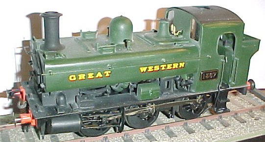
With the kit finished and running, many of the above remarks have been watered down from their earlier form. Of interest is the fact that CRT now only offer their range in ready built form - the kits are no longer available.
Front of the firebox is more matt than |
The glue blob rivets were not too successful |

![]()
![]()
![]()
![]()