It seemed to me that the idea of hanging a '30' size tail rotor assembly on top of a 'Hornet' to produce a flybarless collective conversion was a tremendous overkill. There were discussions on the various forums at the time to the effect that 3mm blade bolts were required to take the loadings involved. When the early '30' sized helis appeared, they all tended to use main blades weighing around 100 grams (early 'Space Baron' blades weighed 130 grams!) with 3mm blade bolts.
There were several cases of blade holder failures (I personally experienced three cases on two different machines), but I never heard of a blade bolt failing, nor of a case of the bolt securing the blade holder to the head failing.
My conclusion from this was that a 2mm bolt would be more than adequate in both cases and that the tail rotor assembly from an electric heli would be more than strong enough. As it happened, I had a complete tail rotor and gearbox assembly for a Kalt 'Whisper'. The most useful feature of this is that the hub was secured to the tail shaft by two 3mm grubscrews. Examination revealed that the threaded holes for these had been tapped in one move, i.e. the thread went straight through the hub.
So, take one standard EO44 from a 'Hornet' and thin down the 'Whisper' tail hub to fit inside it. As the hub would be positioned within the EO44 by the thread, there was no need for any real precision here and it was simply filed down to fit. The next move was to thread a long grubscrew right through the hub and EO44 and cut off the excess screw length.
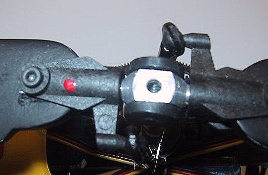
By swapping the hub and EO44 around, a combination was found which positioned the hub centrally. There was around 1/32" clearance between the bottom of the hub and the lower inside edge of the EO44 which allowed a piece of rubber band to be sandwiched in position to provide damping. As an aside, I was never convinced that damping is actually necessary, but it was the easiest answer at this stage. (Tony, in Italy, has produced a similar head using 'Whisper' blade holders and no damping. Click here for a picture).
The sheer ease of the whole operation was added to by the fact that the balls on the blade holder pitch arms are a good fit in the standard 'Hornet' ball links. Thus, I was able to use the existing links. It was necessary to use trailing edge control in order to give some 'Delta 3' effect.
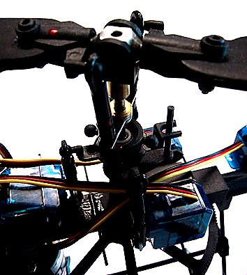
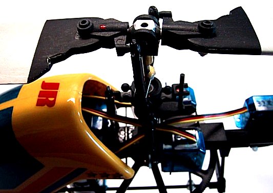
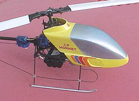
I used the standard swashplate with three servo 90 degree CCPM. After a lot of thought I positioned the servos with one in front of the shaft and two behind. This was partly so that I could use the standard canopy fixing, but a little thought showed that this gave a better weight distribution. The one servo in front of the shaft is more than twice as far away as the two servos behind so the combined effect is to move the C of G forward. A side effect is to make the actual shape of the canopy less critical since the two servos are outside most canopies. The one exception is the JMD 'GPH' style canopy, which will not fit.
The antirotation link was made by drilling out and turning down a 1/8" brass wheel collet (all done in a mini drill). Two saw cuts were made (before turning down) to accomodate two arms from 1/32" piano wire which were soldered in position. The main shaft is one of Warren Collin's titanium items. After several flights, the pin holes in the EO44 started to elongate sideways, so I added a brass tube sleeve which can just be seen in the pictures.
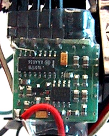
For a reciever, I initially used a GWS 'R4PH' modified to add a fifth channel (actually channel 6 for the pitch). The performance of this receiver never impressed me. While I never actually experienced a glitch while flying, it would frequently twitch when moving the model in close proximity to the trasmitter. A little experimentation established that it would swamp when the orientation of the two aerials was correct and at very close distances.
I resolved this by returning to my original MS receiver (actually a Jeti 4) and modifying that to give the extra channel. After removing the case it proved possible to add a fifth connector with the positive and negative contacts bent around the side of the circuit board and soldered to the leads of connector number four. A short jumper lead from the signal connector to the appropriate pin on the IC completed the job. I then covered the receiver with heatshrink tubing.
I made up some symmetrical blades using 1/2" x 3/16" spruce for the leading edge and 3/4" x 3/16" balsa for the remainder. Like all flybarless set-ups some weight in the blades was going to be necessary, but how much? Informed(?) advice was to use 5 - 6 grams in each blade, which seemed a lot. I used 5 grams. Initial test flights with the blades in bare wood finish were encouraging, but when the blades were covered and finished, control was very sluggish.
I made up another set of blades with 3 grams of lead. When covered and finished, the final weight was 13 grams per blade. This is just a little on the touchy side, but settles down nicely after the first few seconds of a charge when the 'edge' goes off the battery.
The all-up weight of the model with a 7 cell pack and the GWS receiver was just 273 grams and flight time on the symmetrical blades was over 8 minutes. Changing the receiver and using an 8 cell pack raised this to around 290 grams with a similar flight time.
I made up a dual ballraced tail pitch slider by gluing together two standard outer units and trimming back the inner part. I could never eliminate a steady oscillation of the tail. With a freshly charged battery and higher head speed this became increasingly erratic and eventually caused a bad crash. Replacing the standard (sloppy) unit solved the problem and the tail is fine.
My conclusion here is that the poor geometry of the tail bellcrank to pitch slider joint needs some slop in order to work. The side loads generated on the slider are considerable and carbon is hardly the most slippery material even when well lubricated. I have improved the tail response dramatically by making some much lighter tail blades from balsa. My next move is to try a metal tail shaft.
My favourite canopy shape is that used on the early 'X-Cell' helicopters. I made up a couple of balsa canopies based on this shape. These were a little heavy at 12 grams when painted. These seemed to be popular with anyone who saw them so I made up another batch of five with different construction and got the weight down to 9 grams.
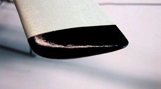
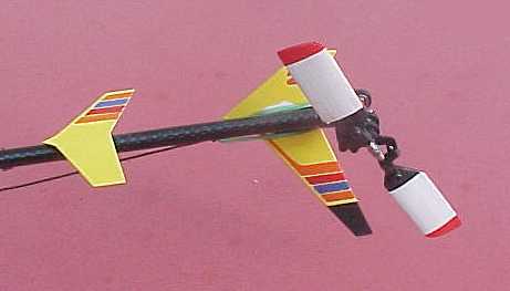
This obviously needed a matching set of tail feathers. A correctly proportioned fin didn't give enough clearance for the tail blades so I extended it and painted the excess section matt black.
Equipment used:
| Receiver | MS Micro Rx 35Mhz with added connector for channel 6 |
| Servos | 4 x Hitec HS-50 |
| Speed Controller | Jeti 05 with external BEC |
| Gyro | GWS PG-03 |
![]()
![]()
![]()
![]()
![]()
![]()
![]()
![]()

![]()
![]()
![]()
![]()